
A decoupling capacitor can be the right value on a schematic and still be poorly connected on the board. Fast current changes respond to the impedance of the complete path. Placement, return routing, and component behavior determine how effectively the capacitor supports the local supply.
Local storage supports fast changes in current demand
An integrated circuit can demand brief current pulses faster than a distant supply can deliver through real wiring. A local capacitor supplies part of that changing current and is then replenished. In a simple ideal model, voltage change equals current times duration divided by capacitance. An illustrative 10mA pulse for 1µs would change an ideal 1µF capacitor voltage by 0.01V if it alone supplied the pulse. Real behavior also includes resistance, inductance, and the rest of the power-distribution network.
The loop includes the return path
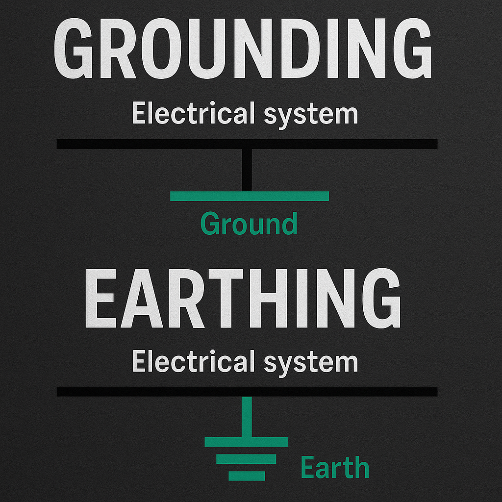
The useful path runs through the capacitor, the device supply connection, the device, and the return connection. Making only one trace short while leaving a long return can preserve a large loop inductance. Analog Devices guidance emphasizes the complete high-frequency path. A ground symbol on the schematic does not make every physical ground point equivalent at fast edge rates. Board layers, vias, plane spacing, and routing affect the actual impedance, so a simple distance rule cannot describe every board architecture.
A real capacitor stops behaving like an ideal one
Equivalent series resistance and inductance change impedance with frequency. Near and above self-resonance, the behavior differs from the simple capacitance equation. Ceramic capacitance can also change with applied DC bias and other conditions, depending on dielectric and construction. Read the component data and the IC recommendations rather than selecting only the printed capacitance and voltage rating. Adding more nominal capacitance does not guarantee better high-frequency support if the package and connection inductance dominate the relevant current path.
Bulk and local capacitors perform related but different jobs
A larger capacitor near a power entry point can support slower load changes and cable effects, while local components help at individual devices. The required combination depends on the supply, load spectrum, layout, and regulator stability requirements. Arbitrarily paralleling many values can also create impedance interactions that need evaluation. Start from the manufacturer reference design and layout guidance, then validate the actual board. A circuit that works at idle may reveal supply problems only when several loads switch together.
Measure the rail without inventing a probing problem
A long oscilloscope probe ground lead can pick up interference and show spikes that exaggerate or obscure the real supply behavior. Use an appropriate low-inductance probing method and verify the reference connection and instrument limits. Compare measurements at the relevant device pins and operating conditions. For low-voltage prototype work, make layout changes with power removed and preserve component polarity and ratings. Do not apply generic decoupling advice to internal mains circuits or alter regulator output capacitance without checking the design requirements.
What to check before you act
- Follow the IC decoupling and layout recommendations.
- Minimize the relevant current loop, including its return.
- Check effective capacitance and impedance at operating conditions.
- Use a suitable probing method to evaluate the supply waveform.
Common questions
Is the nearest capacitor always the best connected one?
Not necessarily. The complete supply-return path and board structure determine its effective connection.
Will a larger capacitor fix every supply spike?
No. Connection inductance, component behavior, regulator stability, and measurement artifacts may dominate.
The practical takeaway
Decoupling is a component-and-layout problem. Choose suitable capacitors, provide a low-impedance local path, and verify the actual supply behavior under the load conditions that matter.
References and further reading
- Analog Devices: Decoupling and physical current paths
- Analog Devices: Local supply capacitors and connection inductance
Numerical scenarios are illustrative unless identified otherwise. Follow the exact product instructions; component ratings and local installation requirements can differ.