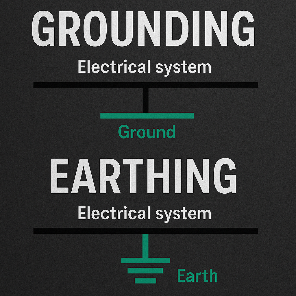

The ground clip on a conventional bench oscilloscope probe is usually connected to protective earth through the instrument. Clipping it to an arbitrary circuit point can create a short. A probe reference is an electrical connection, not a harmless marker telling the screen where zero should be.
The ground lead can connect the circuit to earth
Many mains-powered bench oscilloscopes have their input connector shells and probe ground leads connected to the instrument chassis and protective earth. The exact arrangement must be confirmed from the model documentation. When you attach the ground clip, you can therefore establish a conductive path from that circuit node to earth. If the node is already at a different potential, substantial current may flow. The danger exists before a useful waveform appears, so checking the display afterward cannot validate the connection.
Channels often share a common reference
On a typical grounded-input scope, the ground clips of multiple channels are electrically common. Attaching one to a circuit common and another to a different node can short those nodes together through the instrument. Selecting a mathematical subtraction function does not remove that physical connection. Two ordinary single-ended probes are not automatically equivalent to an appropriately rated differential probe. Read the input architecture and probe instructions before planning measurements across components whose terminals are both away from the established reference.
Low-voltage circuits can still be disturbed or damaged
A short through the probe ground can damage a low-voltage circuit even if electric shock is not the dominant hazard. Connections through USB, a computer, another instrument, or a power supply may already establish an earth reference. Adding the scope can complete a path that was not obvious from the circuit diagram alone. Map the real connections in the entire bench setup. An isolated adapter feeding the device does not guarantee that every signal node remains floating once other cables are attached.
Differential and isolated instruments have their own limits
A suitable differential probe measures between two inputs within specified differential and common-mode limits. An isolated-input instrument uses a different architecture, with its own ratings between inputs, channels, and earth. Neither description permits unlimited voltage or arbitrary use. Probe attenuation, frequency-dependent ratings, measurement category, and accessories also matter. Tektronix explains these distinctions in its probe guidance. Hazardous measurements belong to qualified personnel using equipment explicitly designed and rated for the application, with the full connection plan established before energizing.
Never defeat protective earth to make the scope float
Removing the earth connection from an ordinary grounded oscilloscope can place hazardous voltage on accessible parts and defeat its intended protection. An improvised mains isolation arrangement is not a substitute for a properly designed isolated measurement system. For low-energy learning, use a documented circuit reference and verify that the complete setup permits the intended connection. Disconnect power before rearranging leads as required by the procedure. If the reference relationship is uncertain, stop and resolve it from the equipment manuals rather than experimenting with the ground clip.
What to check before you act
- Confirm the scope input and protective-earth architecture.
- Account for shared channel grounds and other connected cables.
- Use a suitably rated differential or isolated system when required.
- Never remove protective earth to improvise a floating measurement.
Common questions
Does channel subtraction isolate two ordinary probes?
No. Mathematical subtraction does not disconnect their physical ground leads or change the input ratings.
Is a battery-powered instrument always safe to float anywhere?
No. Its isolation design and voltage ratings must explicitly support the intended measurement.
The practical takeaway
Plan the ground connection before the signal connection. A scope probe changes the circuit electrically, and the correct measurement method must respect the entire system of references, isolation, and ratings.
References and further reading
- Tektronix: Probe grounding, differential, and isolated measurements
- Tektronix: Single-ended probe reference limitations
Numerical scenarios are illustrative unless identified otherwise. Follow the exact product instructions; component ratings and local installation requirements can differ.